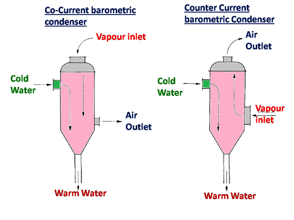
Patibar Chemical OP 19 May 13 0421. Multi-jet Multi-jet spray type Multi-spray and Counter-current designs.
Condenser Calculation Using Thermo Utilities V2 0 Ms Excel Add Ins
N X A X V Length of the tubes required 166624.

. H overall heat exchange coefficient kWm 2 K S area of the heat exchanger m 2 ΔT ml K The value of S can thus be calculated as a 1st approximation of the heat exchanger size. We have the problem of space constraint. Handbook of Mechanical Engineering calculation Second Edition by Tyler G.
Barometric condenser design calculation Written By teachman Wednesday March 23 2022 Add Comment Edit. Its normally recommended that a 34 foot barometric leg be provided which allows the system to pull a pure vacuum and still allows the water and condensate to drain freely. DESIGN CALCULATIONS FOR CONDENSER Inlet temperature of the process stream T1 45 o C Outlet temperature of the process stream T2 45 o C Inlet temperature of the water t1 25 0 C Outlet temperature of the water t2 40 o C Mass flow rate of the process stream m 8060 Kghr Enthalpy of Vapors of Process Stream 1940 KJKg.
Initial condenser widthLD mm. Design when vacuum equipment is placed in a building or an ele-vated structure. An air-cooled condenser is typical of a tube-side condenser.
A Pi X d X N X L Diameter of the condenser required 74749. A common hazard in barometric or shell-and-tube condenser tailpipes is accumulating gases. Water The heat transfer in tube is given by effectiveness Calculation of pressure drop of tube side to evaluate the of heat exchangerCmin Ttubeinlet Tairinletlength of tube temperature at the outlet We get heat transfer in Wtube this.
Cold injection water is conveyed by a central pipe up the length of the body to the rain tray. The Sugar Engineers condenser design is the of the rain-tray type. The hotwell or in the condensing fluid outlet connection for the low level type barometric condenser.
Air cooled condenser design calculation excel. Condenser Design has had 1 update within the past 6 months. Barometric Leg Design.
It is probably the ideal type where load conditions are constant and there is little air leakage. Online calculations for barometric condenser design. The chemical process engineer must be familiar with this kind of calculation not only to do the design but also in the case of the third part project review and.
OBJECTIVES equation Design of Air cooled condenser to avoid the wastage of Cmin is given by Wmk. The simplest design of all barometric condensers and requires no auxiliary air pump or pre-cooler. Because of some TOC Total Organic Compat utilities issue proposed to divert the stream to other existing vessel.
A typical forced-draft air-cooled condenser is depicted in Figure 4. Barometric Condenser Design Calculation. The Barometric condenser will perform the VLE calculations on the species specified by the user in the VLE block.
Condensate from a shell-and-tube condenser or cooling water. Download Condenser Design for Windows to perform thermal design calculations for shell and tube condensers. Circuits numberNB flow per circuit.
H for condensers is often in between 75 to 1100 kcalhm 2 c 01 to 13 kWm 2 K. We are United Heat Exchanger providing solution for Air condensation system for all types of Thermal Power plantsIn systems involving heat transfer a. As 1 of Hg equals 1133 feet of water a minimum barometric leg of 295 feet is required.
This Multimedia Edition contains interactive features that bring the rigorous and authoritative material from HEDH to life. The temperature rise across the barometric is very helpful since it can aid in calculating the duty by the following formula. Fin style0Straight 1Slot 2Triangle wave 3Sine wave Tube material-1See notes 0Copper 1Steel 2Aluminum.
Duty Area Number of tubes ShellTube velocities flooding velocity and operating velocity for reflux condenser Reynolds numbers Condensation heat transfer coefficient Condensation flow regime Number of Baffles and Baffle spacing Scale resistance dirt factor Overall heat transfer coefficient for. The owner or operator must calculate the leak. FOR EDUCATIONAL PURPOSE ONLY DO NOT USE THIS METHOD FOR DETAIL DESIGN ALWAYS CONSULT A REPUTABLE SUPPLIER FOR DETAIL DESIGN Condenser sizing calculation tool Input Results Orientation Heat exchange area m2 Condenser Horizontal Number of tubes Tube length m Tout Tin Cooling fluid Number of passes Water Overall heat exchange.
Note that this is the minimum barometric leg height. June 30 2018 September 6 2019 hiadmin Heat Exchanger 4 Comments on Air Cooled Condenser. The air flow is driven by fans either in forced- or induced-draft mode.
Metric pressure for calculation and taking 80 of the theoretical. The Multi-Jet Condenser is also used where the vacuum handled is not high and a moderately large terminal difference is permissible. Air inlet speed 0Ignore.
Ad Manufacturer of Barometric Condensers vacuum components and systems. A down flow type surface condenser is designed to handle 110 TPH of steam the steam enters the condenser at 012 kgcm2 absolute pressure and 09 dryness fraction. In one of our unit the existing barometric leg from a two stage ejector-condenser system is routed to OWS.
GPM PPH x 1000 T 2-T 1500C p SG GPM gallons per minute of condensing fluid. This is normally H2O but it may be any species with VLE information in the Species Database eg. Detailed calculation than displays many calculated variables such as.
P Lt x Rt x R2 x R1 Re1Re2Re3 HEI for Surface Condenser-. DTube OD X sqrt no of tubes 027 Pressure drop across the condenser. It consists of a tube bundle normally with finned tubes over which air flows in crossflow.
Barometric condenser design calculation Valentines Day is approaching it is just per month absent but there are a lot of stuff to organize from dresses towards the ingesting location from bouquets to the gifts baskets Now we have to rearrange everything for our family and friends. Barometric leg height definition is very important to condenser performance under vacuum conditions because the wrong assumption can lead to condenser flood and poor plant performance. Condensate leaves at 45 C calculate the quantity of cooling water required condenser inlet and outlet cooling water temperatures are 29 C and 37 C respectively.
Multimedia Edition of Heat Exchanger Design Handbook HEDH is the standard reference source for heat transfer and heat exchanger design. Air Cooled Condenser.
Condenser System Vacuum Equipment In Sugar Single Entry Condenser

Surface Condenser Difference Between Jet And Surface Condenser Thermal Power Plant Condensation Surface

Barometric Leg Technical Data Dekker Vacuum Technologies
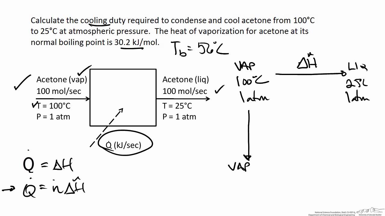
Energy Balance On A Condenser Youtube
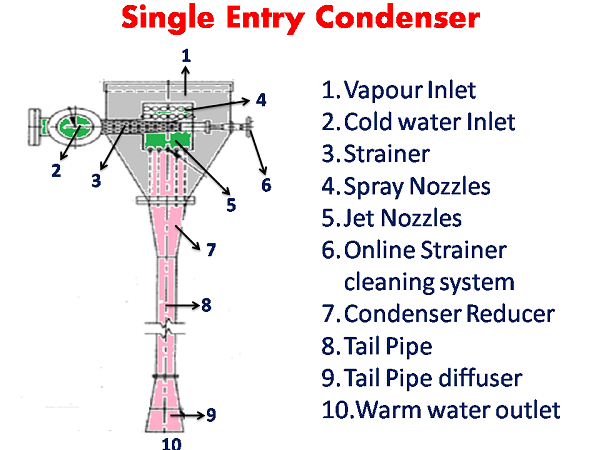
Condenser System Vacuum Equipment In Sugar Single Entry Condenser

Barometric Jet Condenser Complete Explanation Youtube

Condenser Calculation Using Thermo Utilities V2 0 Ms Excel Add Ins
Surface Condenser Difference Between Jet And Surface Condenser
0 comments
Post a Comment